From prototype parts processing to mass production

High quality prototype products
at low cost in a short lead-time

Category of press stamping process

Tandem process

  • Several presses are laid out in tandem arrangement and one production line is composed.
  • Similar to a transfer process, each stage is equipped with an independent die. Normally, an operator places a product each time.
    Sometimes robots or other carrier devices are used to feed products automatically.
  • This process is fit for low volume production or a short process. Because of each press standing alone, flexible production is allowed.
Tandem process

Progressive process

  • All processes are assembled in a die and this is set up in a progressive press. Coil material is fed from one end of the press and the parts are stamped from one stage to the next leaving a certain amount of material.
  • A coil feeder is needed, but a complicated transferring mechanism is not required as with the transfer press. This allows a higher efficiency in production.
  • However, when parts are separated from the material, miss-match allowable is left.
  • This sometimes causes an ill effect on the function of the parts such as fatigue endurance. Thus, the die needs to be set up carefully.
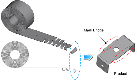
Progressive process

Transfer process

  • Carrier and fingers at each stage allows products to be transferred from one die to another in a press.
  • There are two types of fingers. One is 2 axis feed (X and Y) that moves horizontally and the other is 3 axis feed (X, Y, and Z) that moves in three dimensions.
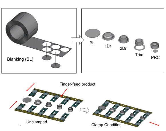
Transfer process

Inquiry and request form

Keiaisha Prototype Fabrication Group provides prototypes and mass production parts for automobiles, construction machineries, industrial machineries, etc.
Please contact us by phone at +81-45-804-8812 or fill out the inquiry form.

Please fill out your information.

Company:
Division

Case studies of our engineering

Suggestion for the press plate shape

Material: SAPH440
Material thickness: 4.5 mm

CAE analysis on base parts

Inspect resonant frequency, auxiliary machine vibration, bracket emergence stress, etc. and compare with the results from the actual machine.

CAE analysis on base parts

Validate customer's criteria using CAE analysis and determine the suggested design shape.

Apply single body vibration endurance test

Apply 107 time resonant frequency and stress measurement, validate for the existence of cracks. This would allow to create an improved shape easily.

Adoption to mass production engines

The simulation study on 3D CAD make interference at assembly visible. The issue can be resolved beforehand to make smooth production launch possible.

Testing and layout equipment

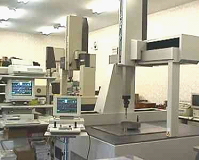
  • Coordinate measuring machines
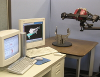
  • 3D graphic image layout machine
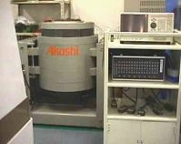
  • Vibration testing machine, stress monitor
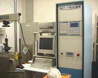
  • 10 ton fatigue testing machine